
|
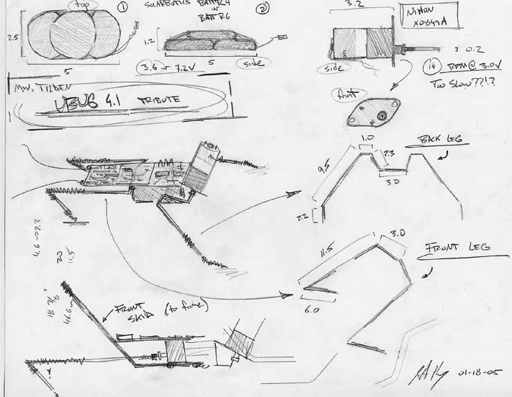
mwt UBUG 4.1 tribute (Tribute) |
||
|
This page is all about my attempt to replicate one of my favorite robots, UBUG 4.1. This particular robot was designed by Mark Tilden and is a two-motor walker that uses a master-slave bicore for control. I have had trouble finding documentation on this particular robot so I've been forced to make some educated guesses in many parts of my design.
|
||
|
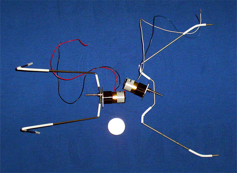
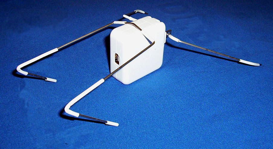
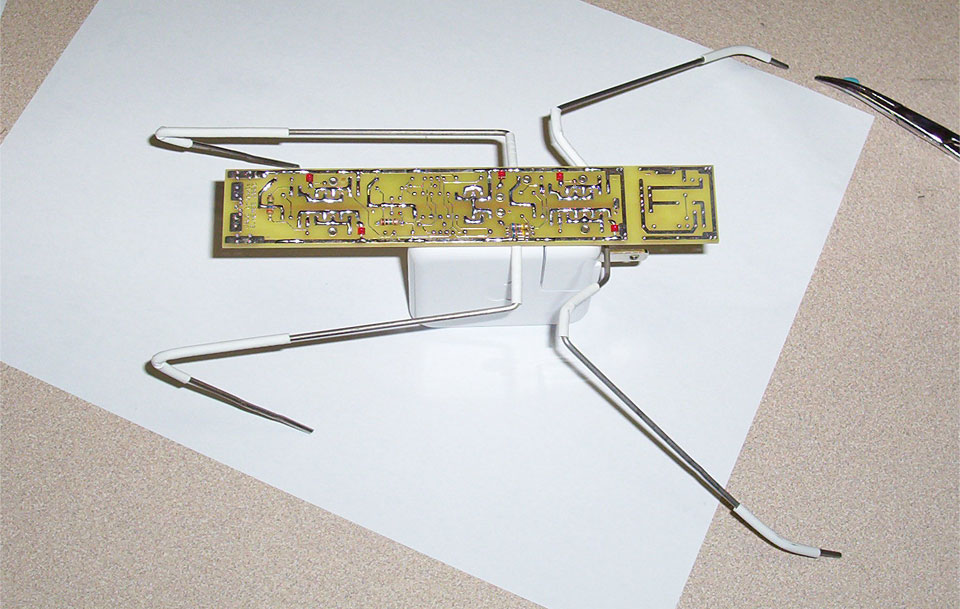
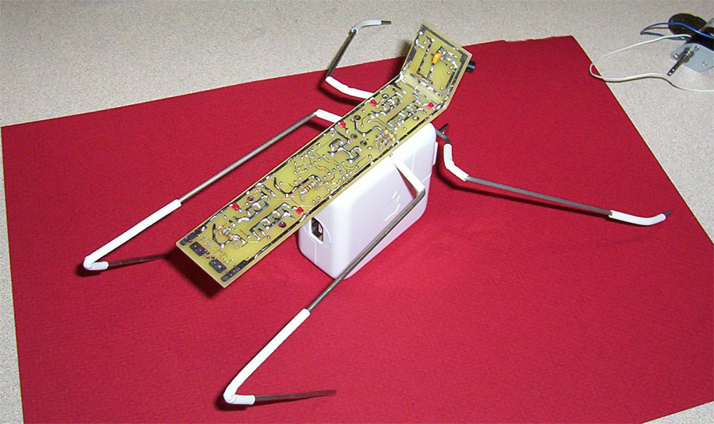
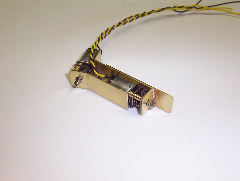
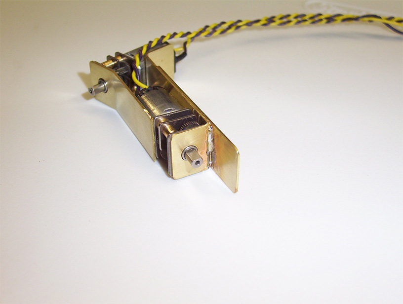
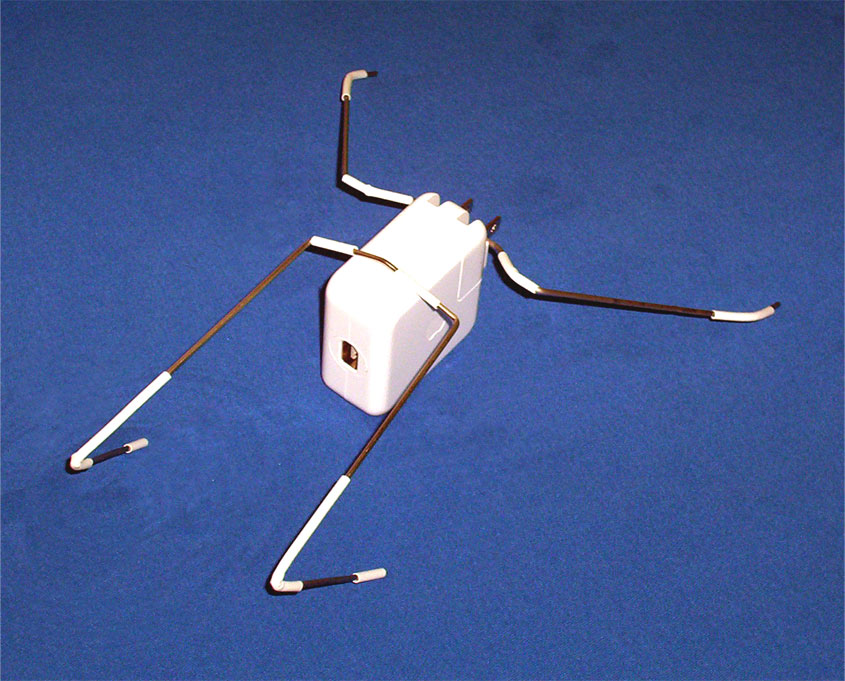
Initial Leg Design This is the first pair of legs I made for the project. After framing up the motors and playing with the legs, I found that the balancing point was not just right. The front legs were too narrow for their length. I also made the decision to go with some Sanyo gearmotors instead of the Nihons seen here. |
||
|
|
|
 |
|
The first set of legs supported by an iPod power adapter |
||
|
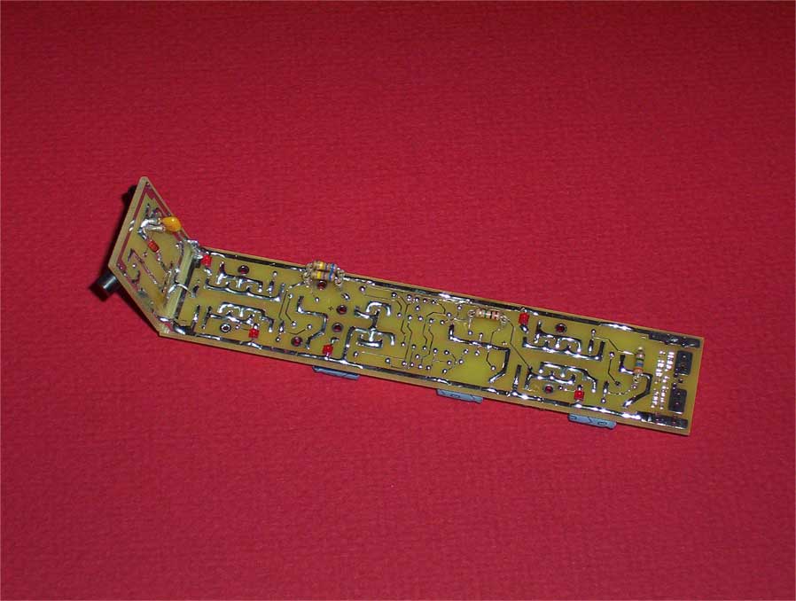
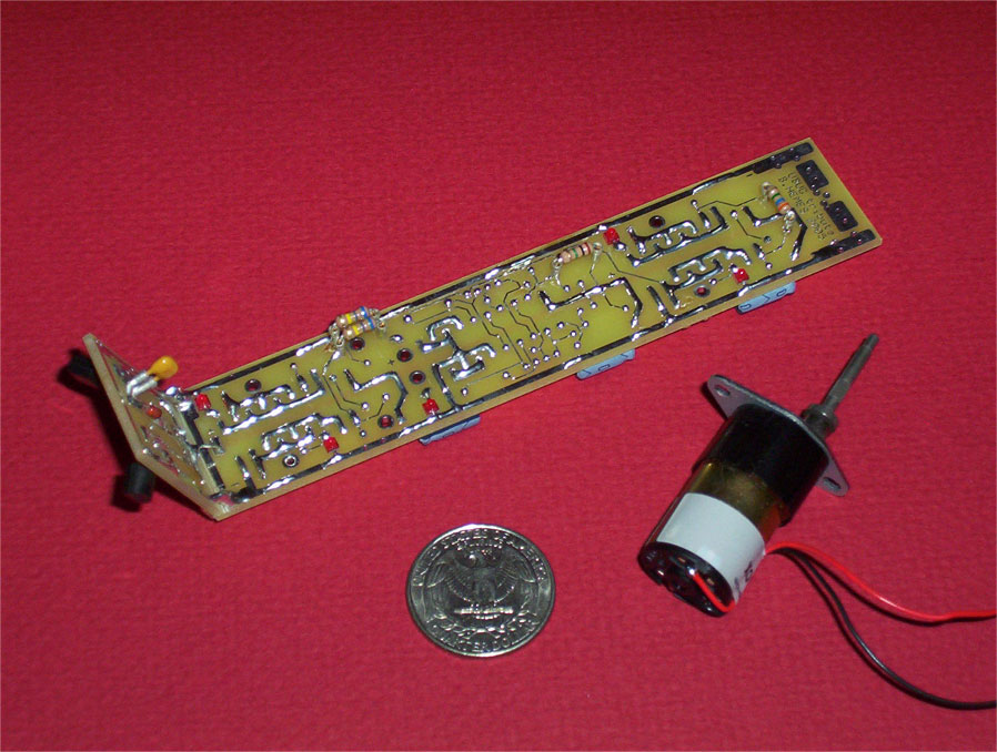
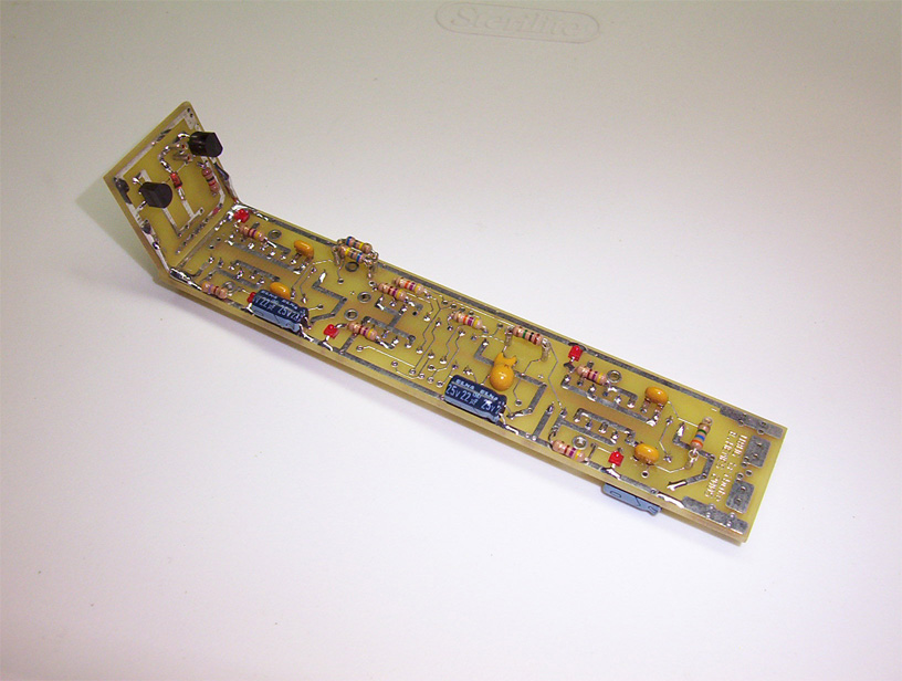
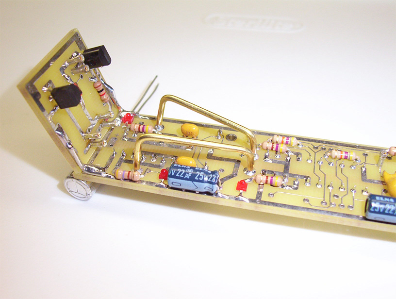
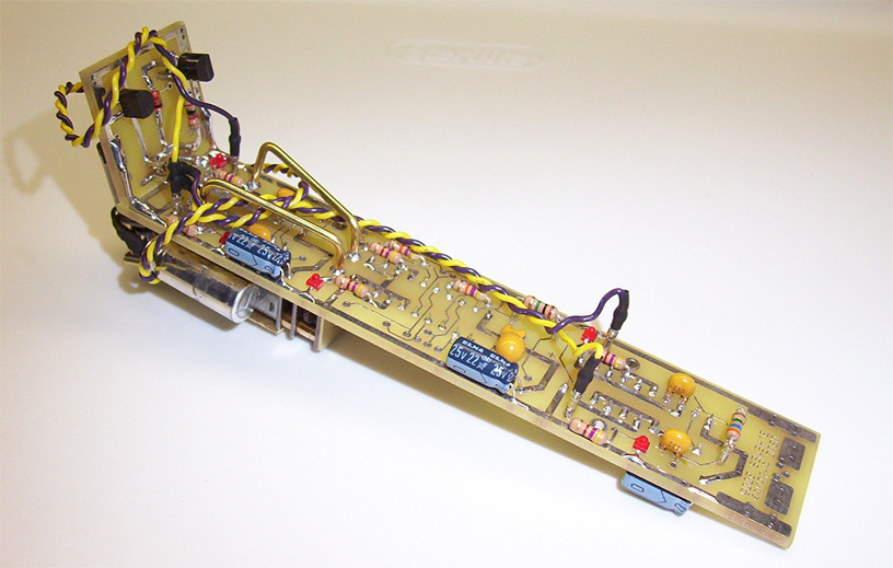
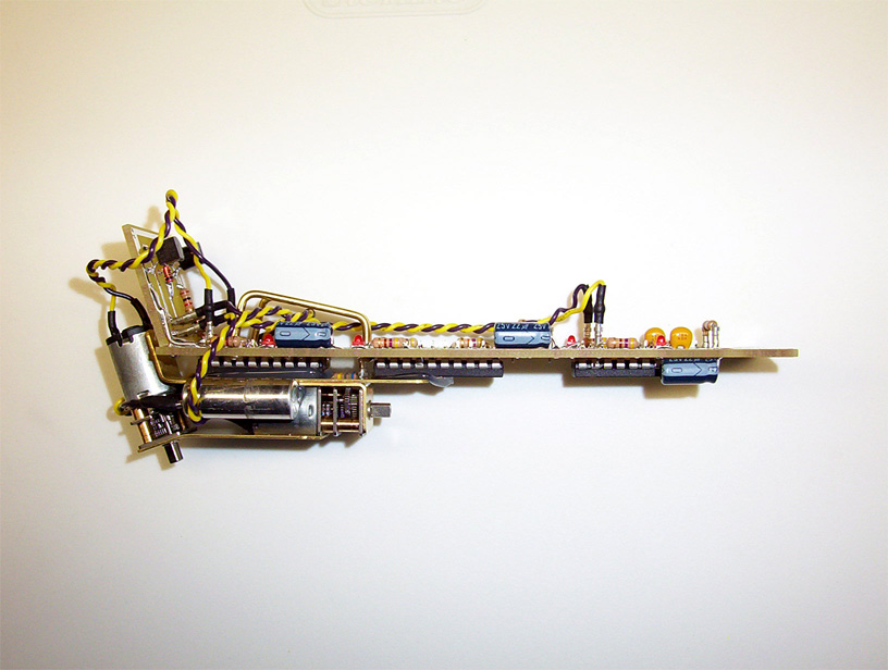
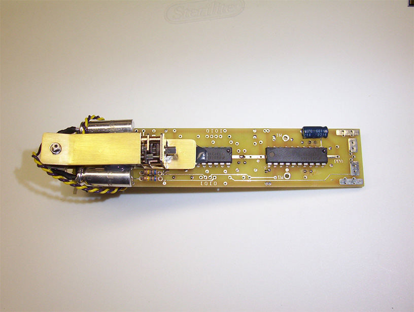
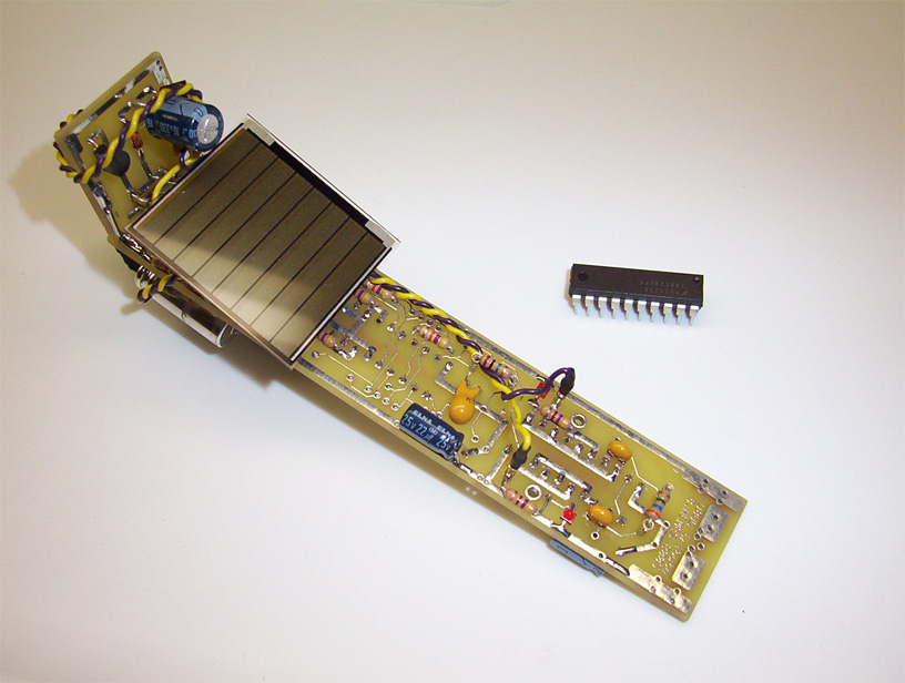
Tribute PCB I decided that a professionally made PCB would give me the look I was going for. I designed the PCB using ExpressPCB and tried to emulate Tilden's original UBUG shape and size. The first two pictures are of the layout. The left PCB picture is without a solar engine while the right has a Miller Solar Engine attached. Each board has to be cut between the bicores and the solar engine and bent upwards to emulate UBUG 4.1's design. |
||
|
|
||
|
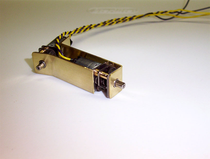
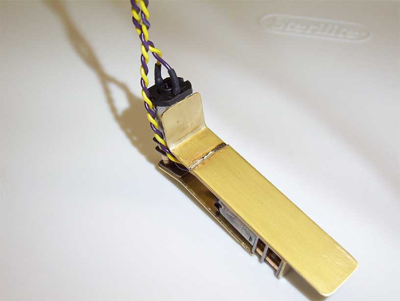
Tribute Chassis
|
||
|
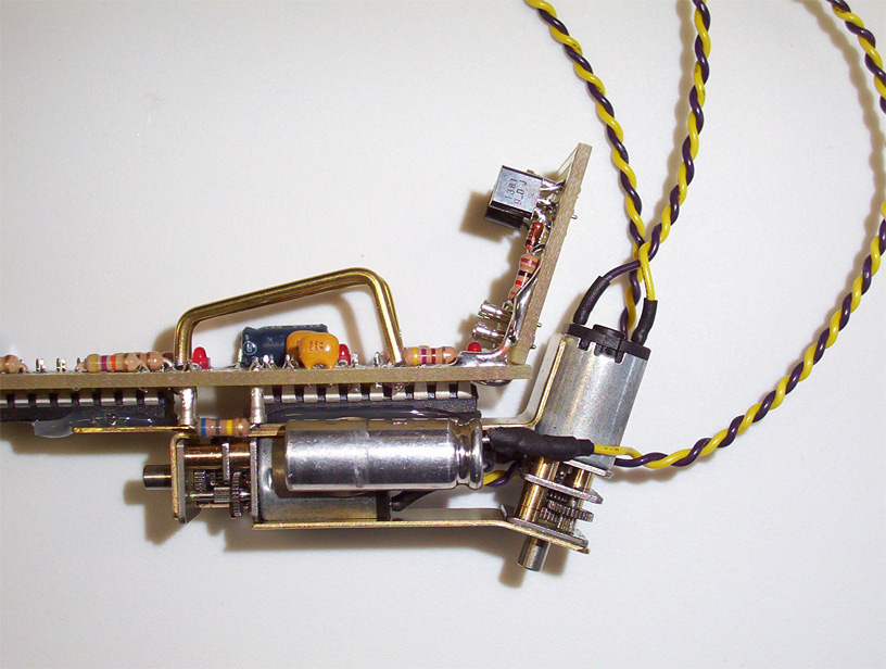
Final Body Assembly The chassis is secured to the PCB with a bead of hot glue. The hot glue holds the PCB securely enough to the chassis so as not break off but can be removed without harm if necessary (CA glue tends to crack and leaves residue when removed). To mount the solar cell, I soldered two 1/16" brass rods to mounting holes on the PCB. I bent the rods to give the solar cell a gentle slope towards the front of the robot. This was mainly for aesthetic purposes but also increases the efficiency of the cell when the robot is heading towards light.
|
||
|
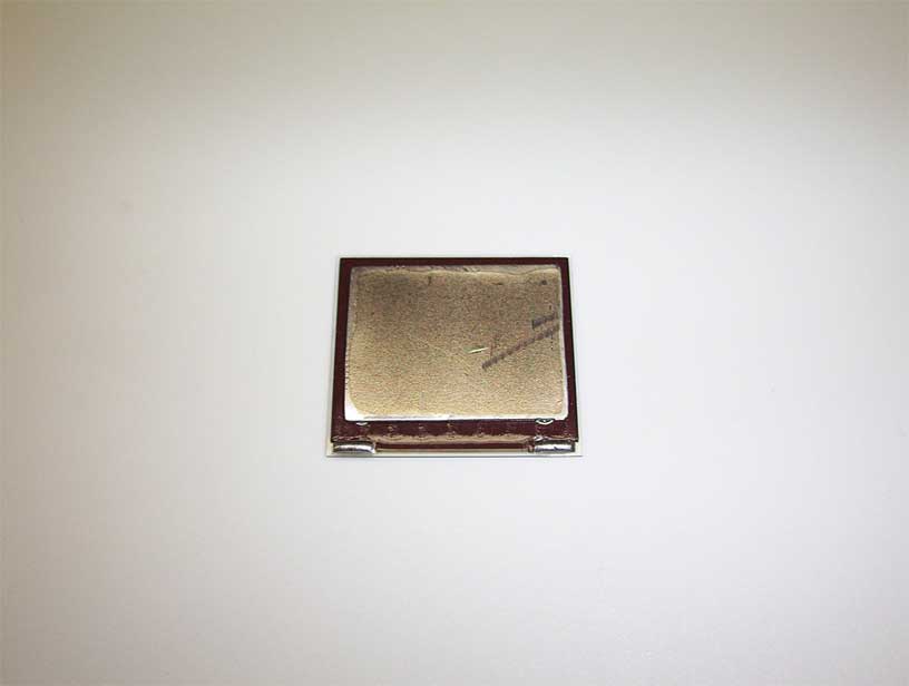
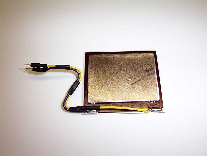
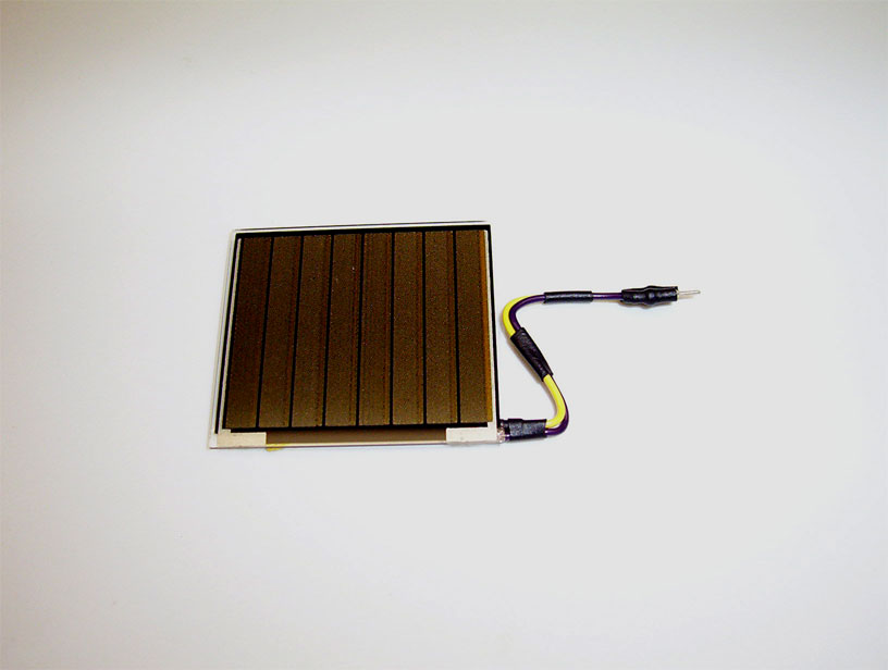
Solar Cell Assembly Here is the finished solar cell. I glued a stainless steel plate to the back of it to protect the fragile solar membrane. The stainless piece glues to the two brass mounts on the body with hot glue, making a strong but removable connection. It necessary the solar cell can be removed by simply peeling off the hot glue and disconnecting the pins from the sockets on the body.
|
||
|
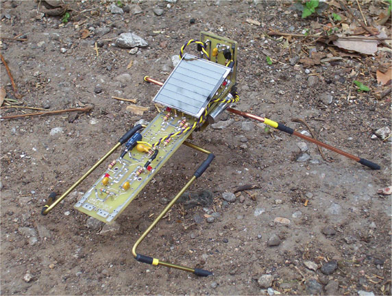
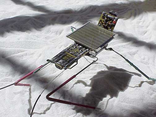
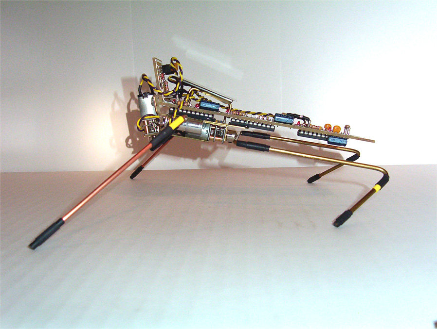
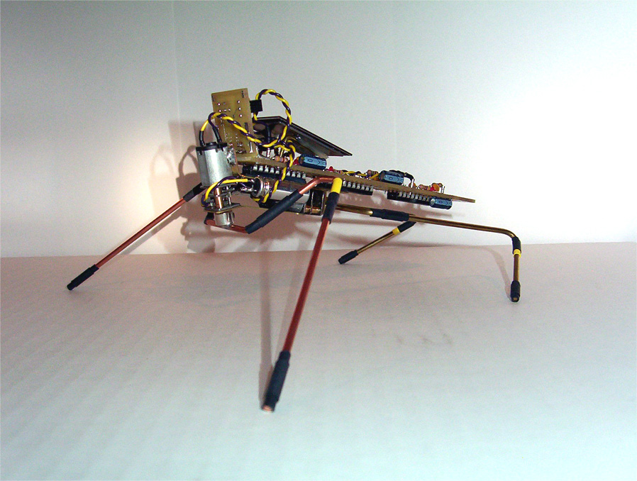
Final Assembly Here are some pictures of the completed robot. Everything went together beautifully and is holding up very well. I am extremely happy with how the robot came out and can not wait to build another.
|
||
![]()