

|
mwt UBUG 4.1 tribute PCB |
|
|
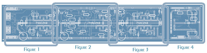
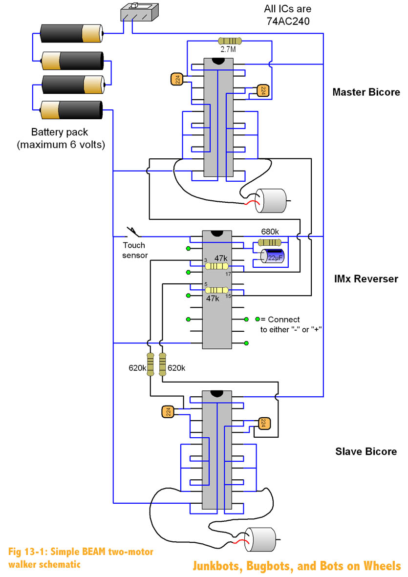
This is my layout of the classic 2-motor BEAM walker. The circuit is a Master-Slave Dual Bicore with an added inverting multiplexer for added reverse capabilities. Figure 1 is the "master" suspended bicore that drives the circuit. The outputs of the master are passed through the inverting multiplexer (Figure 2) and to the inputs of the "slave" bicore (Figure 3). When the inverting multiplexer is activated by a short between the front solder pads, the signals to the slave bicore are inverted, causing the robot to reverse. Figure 4 is an optional Miller SolarEngine that can be used to solarize the circuit. ExpressPCB File: ubug_w_se_V2.pcb For more detailed information on this circuit, see Wouter Brok's article on the Suspended Bicore.
Associated Links: |
|
|
Figure 1 |
|
|
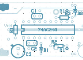
This figure contains the circuitry for the master
bicore. The timing is set by R1, C1 and C2. C3 is the
decoupling capacitor for the 74AC240. The indicator LEDs and current
limiting resistors, D1, D2, R2, R3 are optional. M1 and M2 are the
pads for the front motor of the walker. The two large solder pads in
the upper left of the PCB are used to mount the tactile sensor to trigger
the multiplexer for reverse. When the pads are shorted, reverse is
activated.
Required Components:
Optional Components: |
|
|
Figure 2 |
|
|
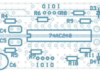
This figure is of the inverting multiplexer for
reverse. Only one half of the multiplexer is implemented in the
layout (Components C5, R7, R9, and R10 are not used but have been wired for
optional experimentation). The reversing time is set by R4 and C4.
R11 is the current limiting resistor for the reverse indicator LED, D4 and C6 is another decoupling capacitor.
Required Components:
Optional Components: NOTE!!!!!! |
|
|
Figure 3 |
|
|
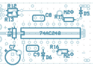
This figure is of the slave bicore. R12 and
R13 along with C8 and C9, determine the phase shift between the front and
rear motors (R14 may be used in place of R12 and R13 to form a second
suspended bicore that runs independently of the one in Figure 1). R15 and R16 are
the current limiting resistors for the optional indicator LEDs D5 and D6. C7 is the third
decoupling capacitor.
Required Components:
Optional Components: |
 |
|
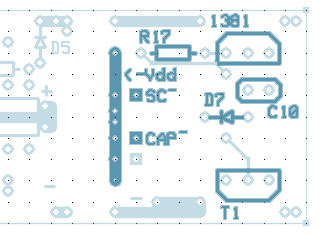
Figure 4 |
|
|
This figure is of the optional Miller SolarEngine to solarize
the circuit. A detailed description of its operation can be found
here. Also included in this figure
are the connection for the solar cell and power capacitor required for
solar operation. If solar operation is required simply connect the
outer ground traces to the main board along with the two power rails (Vdd
and +).
Required Components: |
|
![]()